Corner Relief In Sheet Metal Catia

Catia Sheetmetal Design Corner Relief Youtube
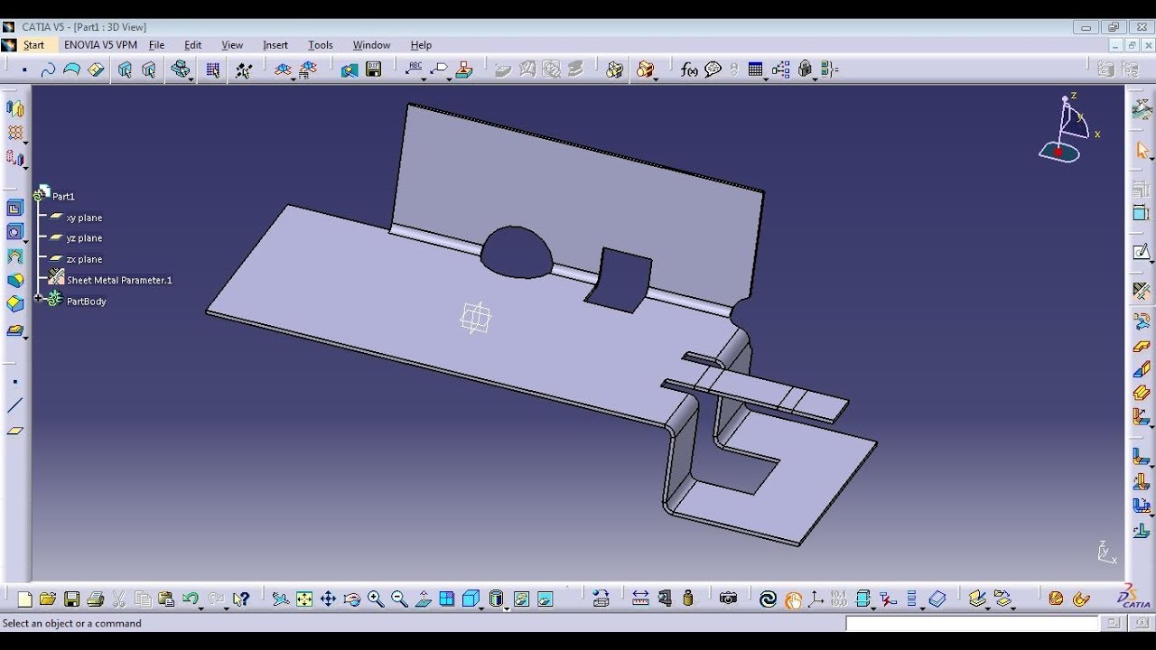
Catia Generative Sheetmetal Design Corner Relief Cut Out Youtube

Catia V5 Corner Relief Sheet Metal Youtube

Solidworks Sheet Metal Forming Tool Exercise Youtube Solidworks Sheet Metal Solidworks Tutorial

Cutout Circular Cutout Corner Relief Fillet Chamfer Sheet Metal Catia V5 Youtube

Pin On Art

Within the tools options general parameters knowledge tab check the load extended language libraries option.
Corner relief in sheet metal catia.

Solidworks Tutorial Sketch Sheet Metal Screw In Solidworks Youtube Solidworks Tutorial Solidworks Sheet Metal

Solidworks Tutorials Q A How Do I Create A V Shaped Sheet Revit

Solidworks Sheet Metal Youtube In 2020 Solidworks Tutorial Solidworks Tutorial

How To Fill Corner Gaps On Sheet Metal Parts Bricscad Mechanical Youtube

Sheet Metal Corner Relief Tools Cad Design Tools Youtube

Solidworks Screw Conveyor To Sheet Metal Solidworks Tutorial Solidworks Tutorial

Solidworks Sheet Metal Lofted Bend Youtube

Solidworks Tutorial Sketch Kitchen Sink In Solidworks Kitchen Tools Sketch Solidworks Tutorial Sketch Kitchen Sink In Solidworks In 2020 Organizer Tricks Sinken

Youtube Solidworks Metal Working Sheet Metal

Youtube Sheet Metal Tools Sheet Metal Metal Tools

Closed Corner In Sheet Metal Solidworks 2017 Youtube

Solidworks Tutorial Corner Treatment Sheet Metal Tutorial Youtube

Pin On Sheetmetal

Solidworks Catia Nx Autocad 3d Drawings Practice Books 100 Pdf 176 In 2020 Mechanical Design Drawing Practice Autocad Tutorial
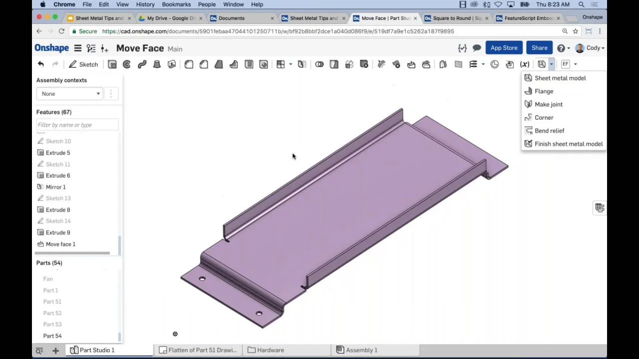
Sheet Metal Tips And Tricks

Solidworks Sheetmetal Close Corner Weld Corner Corner Relief Chamfer Fillet Hindi Urdu Youtube

Pin By Ashish On Projects To Try Solidworks Tutorial Solidworks Mechanical Design

Solidworks Tutorial For Beginners Exercise 23 Youtube Solidworks Tutorial Solidworks Tutorial
Https Encrypted Tbn0 Gstatic Com Images Q Tbn 3aand9gcsyli U0gftpsfsqaxjyymnyf8d4tkuo2xsqdknxb3v47 Lqlg Usqp Cau
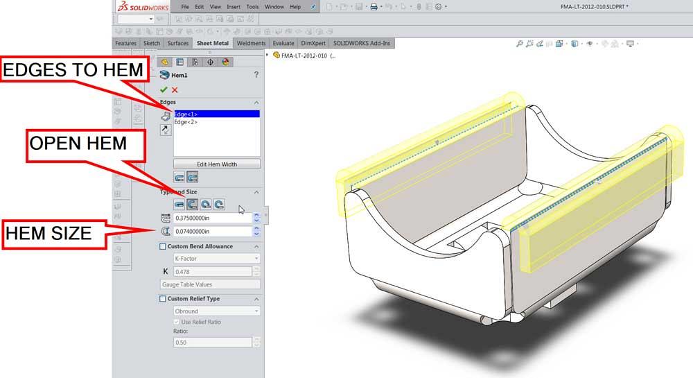
What Sheet Metal Shops Wish You Knew Hems Jogs And Forming Tools

Pin On Solidworks

Cimquest 2 Minute Tuesday Mirrored Sheet Metal Youtube
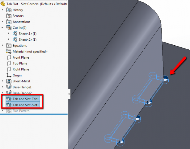
What S New In Solidworks 2019 Sheet Metal Slot Corners

Solidworks Tutorial Sketch Computer Fan In Solidworks Youtube Solidworks Tutorial Computer Fan Solidworks
Source : pinterest.com
